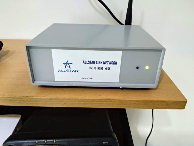
My aim here is to put forward a very simple design for an Allstar node which will be suitable for novice home builders as a first Allstar project. The use of the ARA-1 sound fob means that you will avoid the somewhat intricate and fiddly soldering of the tiny wires involved with the more traditional CM108 sound fob approach. George has done all the hard work for you!
The case I have used is a plastic electronic project box { 130x170x55mm } bought from eBay. I have used the smaller Raspberry Pi 3 Model A+ because it fits nicely in this compact case, if you are using a regular sized Pi 3 then a larger case may be required.
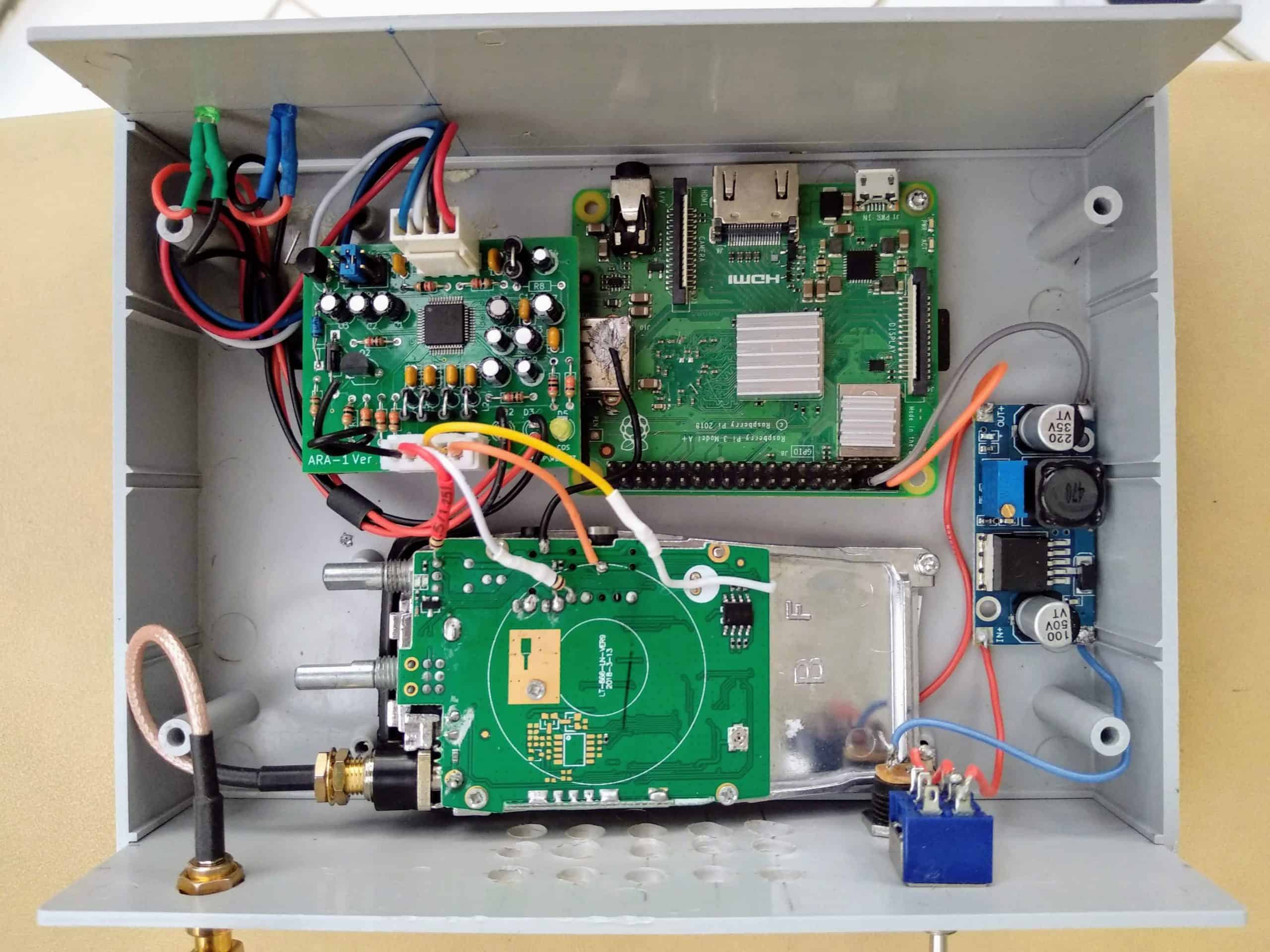
Interior view - Click to enlarge.
The top wires { Blue, white, black and red } on the ARA-1 are already wired to a USB connector, this plugs into the Rpi and the ARA-1 conveniently sits on the USB plug with its supplied adhesive pad.
The black and red wires are soldered to the points where the LEDs were attached on the ARA-1. They connect to the two new LEDs on the front panel.
That just leaves the wires from the lower connector to solder to the points on the radio shown on the photo above. A quiet node is a good node so keep these wires as short as possible to avoid RFI beeps and whistles.
Construction details
Step 1. Modify a Baofeng 888s radio as per the instructions elsewhere on this site.
Step 2. Set up the buck converter to supply 5v for the Raspberry Pi, then put a single 1n5408 diode (or similar) in series with the power lead going to the back of the radio. That’ll drop the voltage about 0.73v or so to meet the requirements of the radio. Details in our More section in the top menu.
Step 3. Obtain a ARA-1 sound fob from George at https://technobygeorge.comBasically you snip the DB-25 connector from the end of the ARA-1 sound fob, cut the wires to length and then just tack them on to the Baofeng 888s at the points shown in the photo above. The two resistors, one on the red wire and the other on the white wire are both 10K.
Step 4.Please refer to the photos on this page for your wiring and final assembly details. The black wire on the ARA-1 sound fob is not necessary.
But note the black wire connecting the radio to the USB housing of the Rpi, this is the ground connection to the radio, make sure you follow this type of configuration to avoid ground loop hums. Meaning, make sure that there is only one ground connection to the radio, this can also be done at various points on the metal heat sink, and the large copper plate with the screw in it located at the centre of the board
The Rx / TX LEDs: All you need do is to carefully remove the Tx and Rx LEDs on the ARA-1 sound fob, attach a couple of wires to the through the hole board points which they occupied and solder on new LEDs to mount on the front panel.
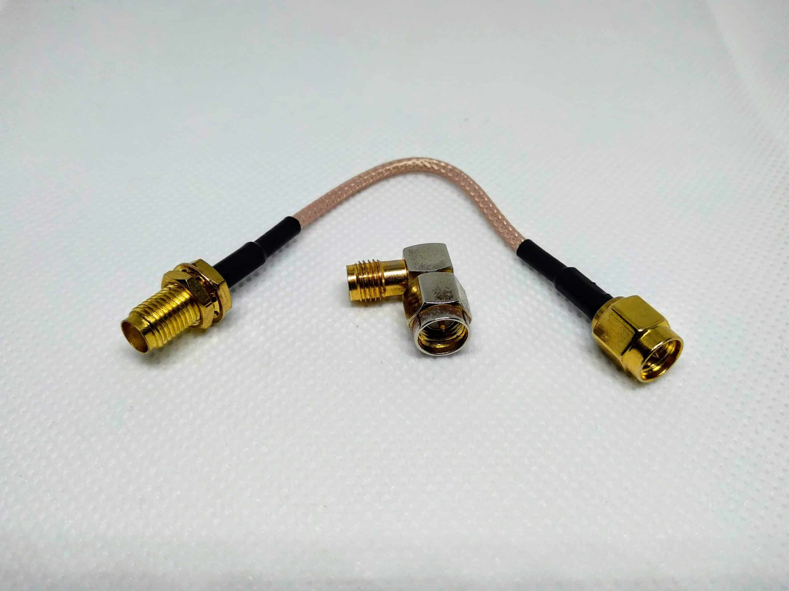
The aerial assembly is shown above, this is a 10 cm SMA male to female lead plus an SMA male to female right angle 90-degree adapter. These are available from eBay, Amazon and elsewhere.
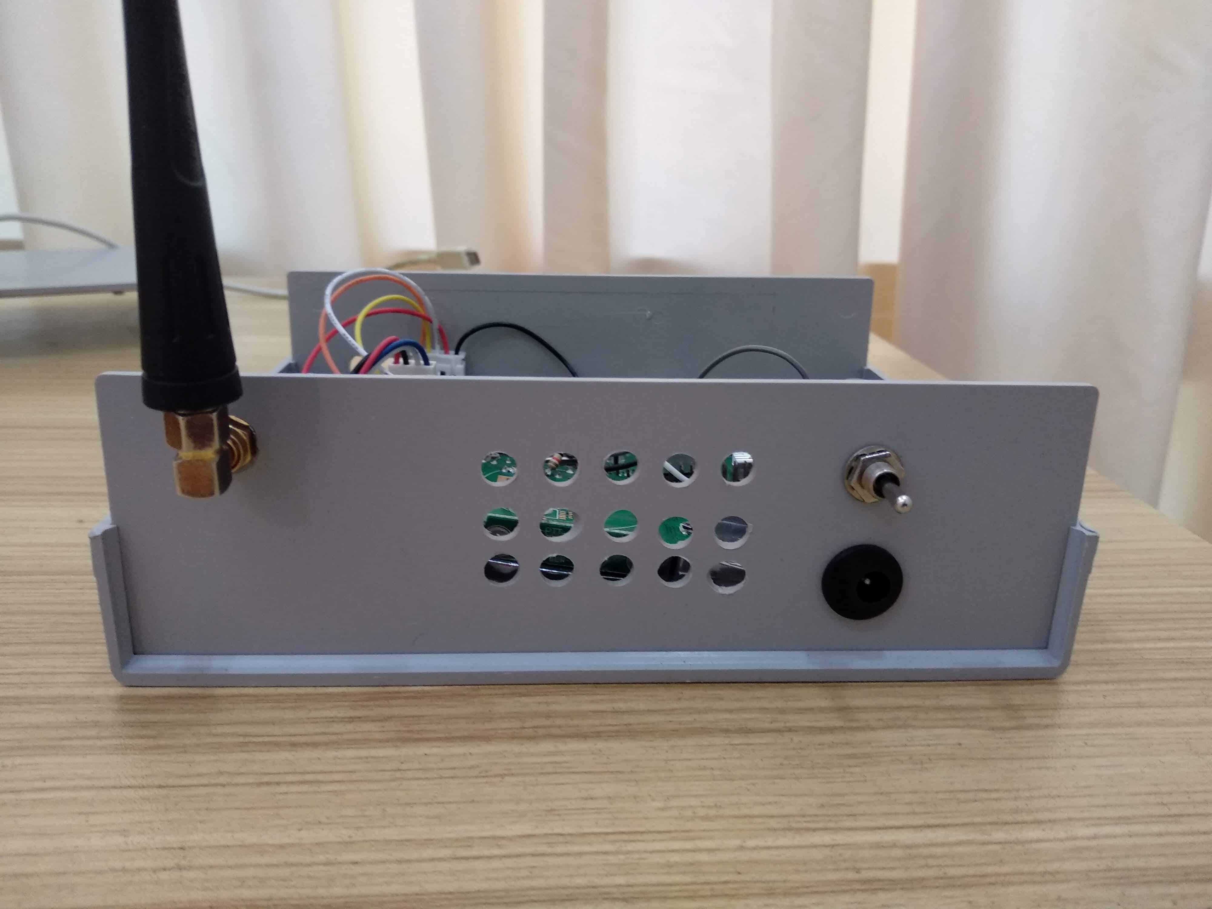
Back panel view.
Once you have completed the hardware build you can learn how to set up the necessary software via my More section.