This page describes a simple method I have been working on recently to modify the CM108 sound fob for use with Allstar, you only need to cut one track and add one resistor, the rest is just wiring.
This latest modification is indeed simple compared to my previous legacy modification designs which you can view via this link: LINK
You may wonder how the simple modification I am going to describe might work without the added transistor and other components on my legacy designs?
The answer is that this simple fob modification will work well provided you go to the SimpleUSb Tune Menu in Hamvoip using Putty or similar and toggle item ” I ” the PTT mode to active high.
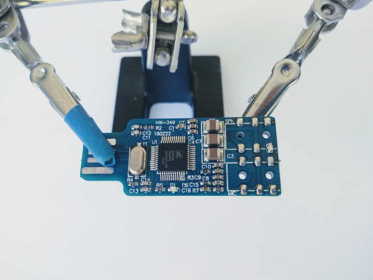
Step 1: Take a new CM108 sound fob and carefully remove the green and pink sockets. This is best done with a heat gun, just apply the heat and let them float off. Don’t force it as this may damage the solder pads, it should then look like the above.
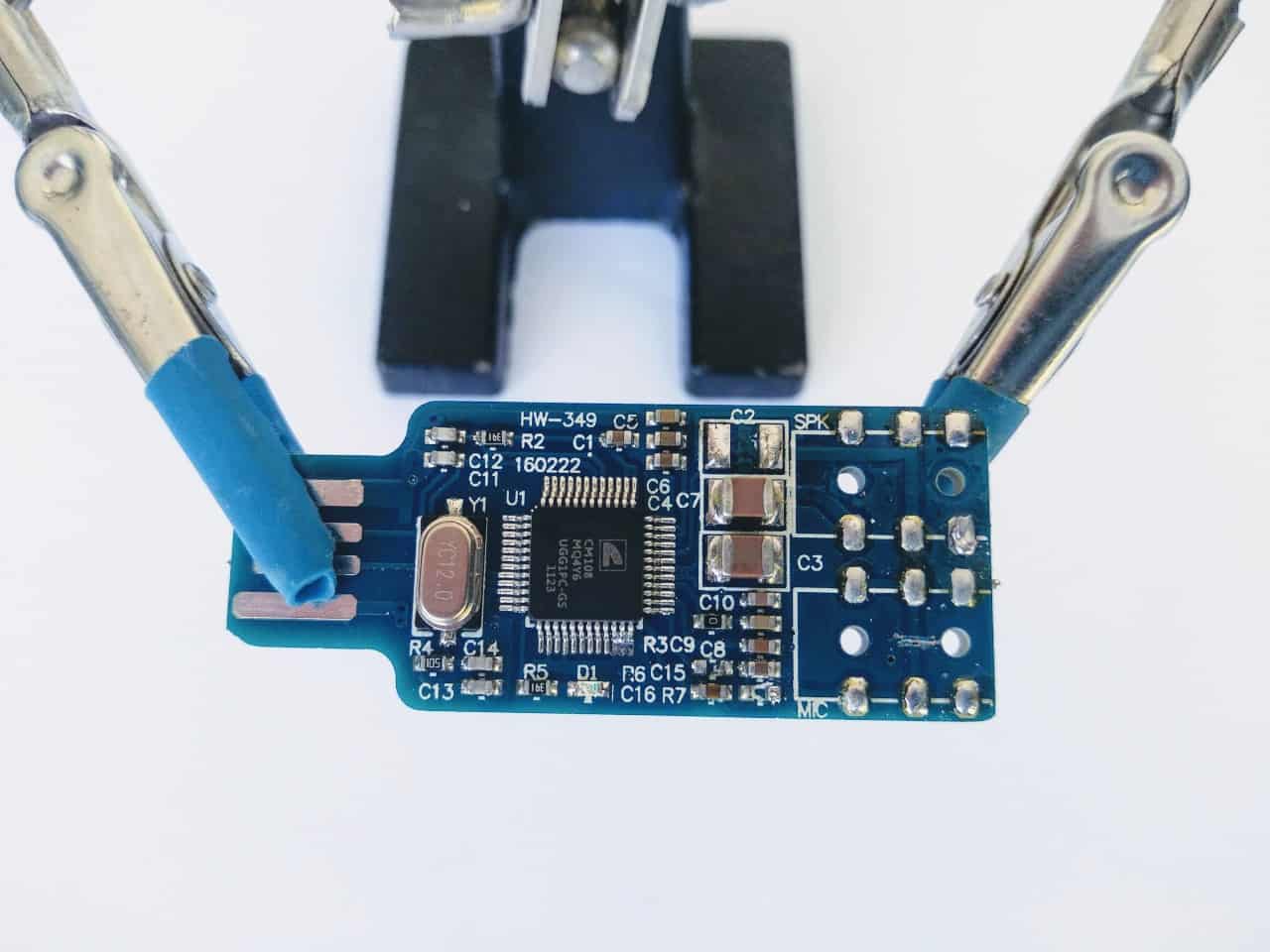
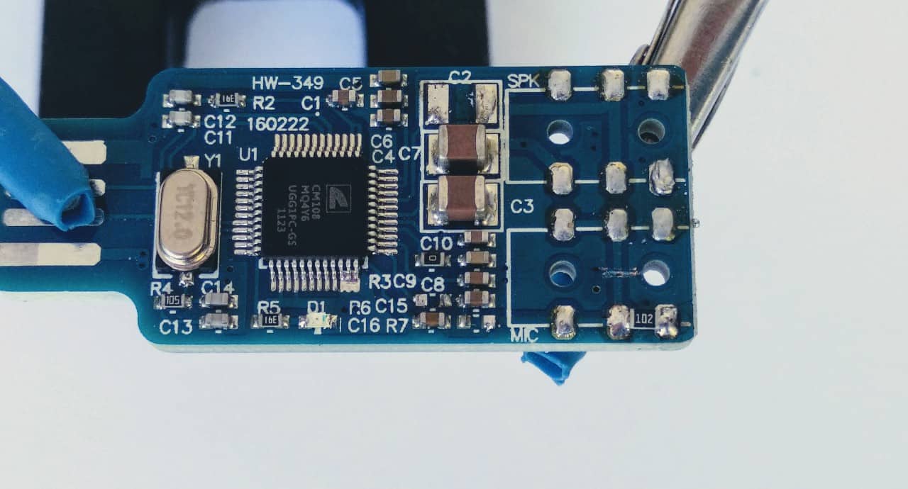
Step 2: Cut one track, remove 3 components
Click to enlarge.
Step2: Cut the tracks in the place shown, this can easily be done with a craft knife, you may want to use a multimeter to check that this was done properly.
Then remove resistors R6 and R7 plus C2, this is easily done with the tip of a hot soldering iron.Step2:
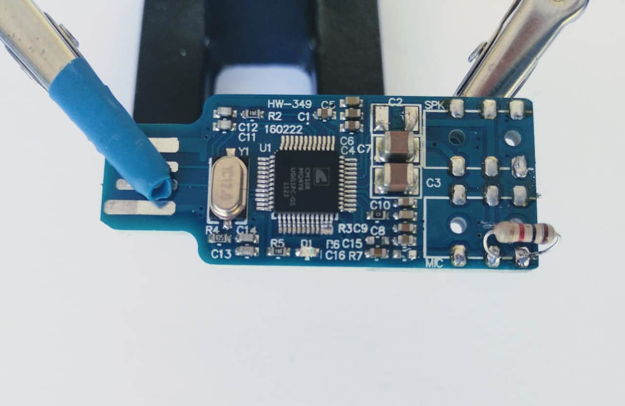
Step 3: Add a 1 K resistor.
Click to enlarge.
Then add a 1K resistor in the place shown. A conventional resistor will work well.
Click to enlarge.
But a surface mount 1 K resistor may be a better alternative. The solder pads are just the right size for this and it does make a neater job.
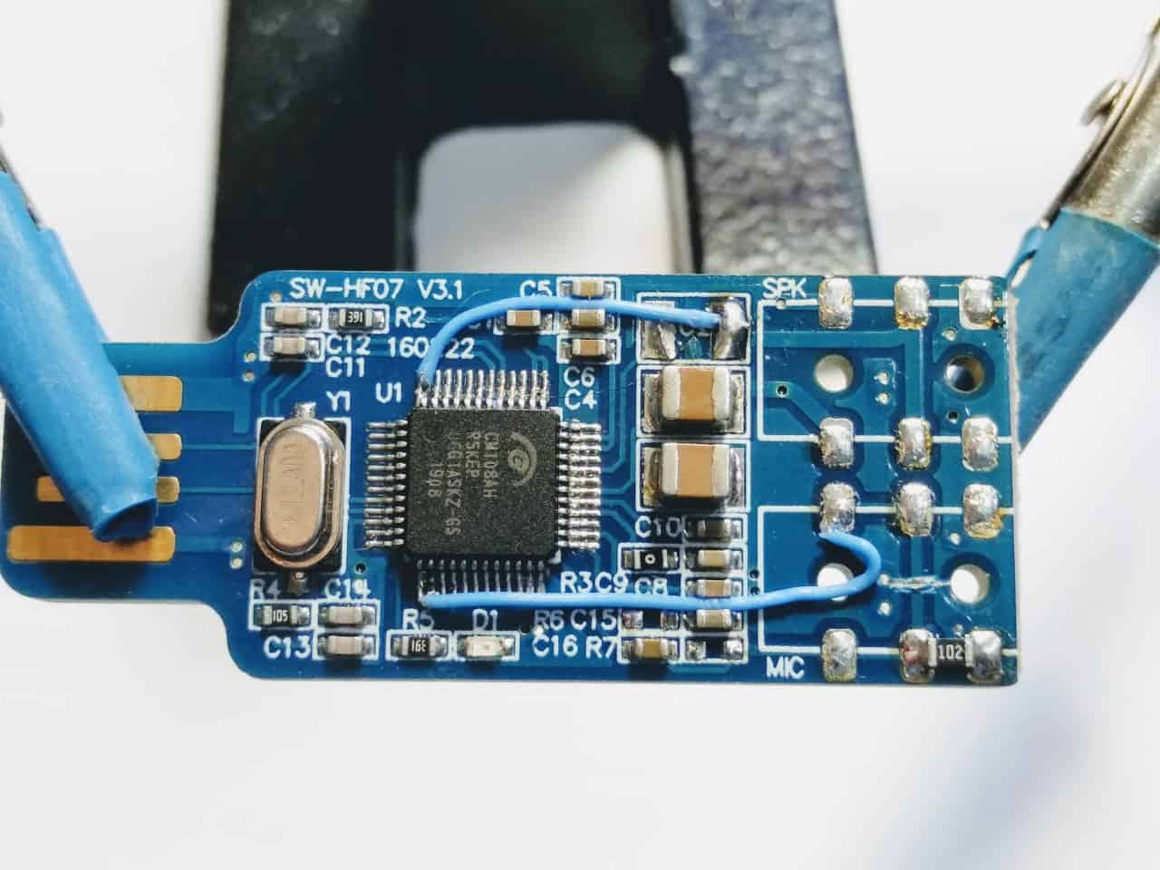
Step 4: Add the fine wiring for the PTT and Cos.
Click to enlarge.
Add the wiring to the pins on the chip as shown.
This may look fiddly, but if you has some means of magnification and use the correct type of wire to attach to the pins on the IC chip then it is quite easy. I use 30 AWG sold silver-plated copper Kynar wire, you can get this from eBay. Of course, other types of wire are suitable, but make sure it is thin.
Just cut your wire to size first, tin it well, apply flux, then hold it against the correct IC pin and apply 1 – 2 seconds of heat from your soldering iron, that is enough to attach it properly.
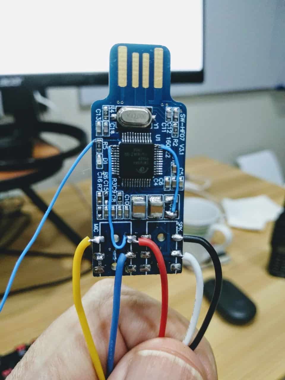
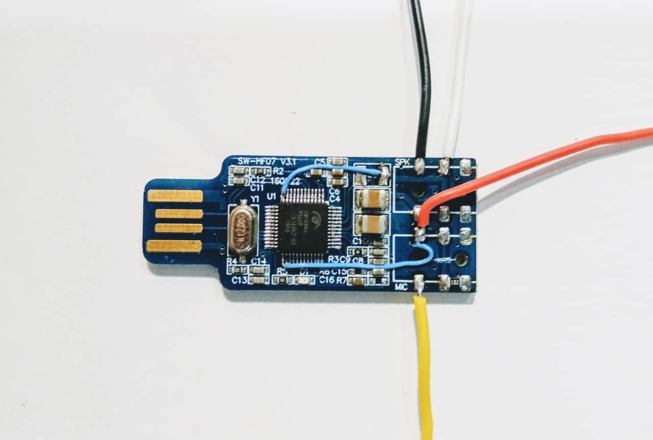
Step 5: Add the hookup wires.
Click to enlarge.
Step 5 is to add the hook-up wires to connect your modified sound fob to the Baofeng 888s radio. I tend to use the same color-coding in my nodes.
Black = Tx
White = Cos
Red = PTT
Yellow = Rx
You can see elsewhere on my site how these four wires attach to the Baofeng 888s
At this point the fob should be fully functional and if you have coding ability to add the front panel indicator lights via the GPOI pins on the Rpi then this is all you need. This, however, does demand quite a high degree of coding ability and so is really outwith the scope of this Allstar for beginners website. I will go on to describe a simple method for wiring the indicator lights without any coding.
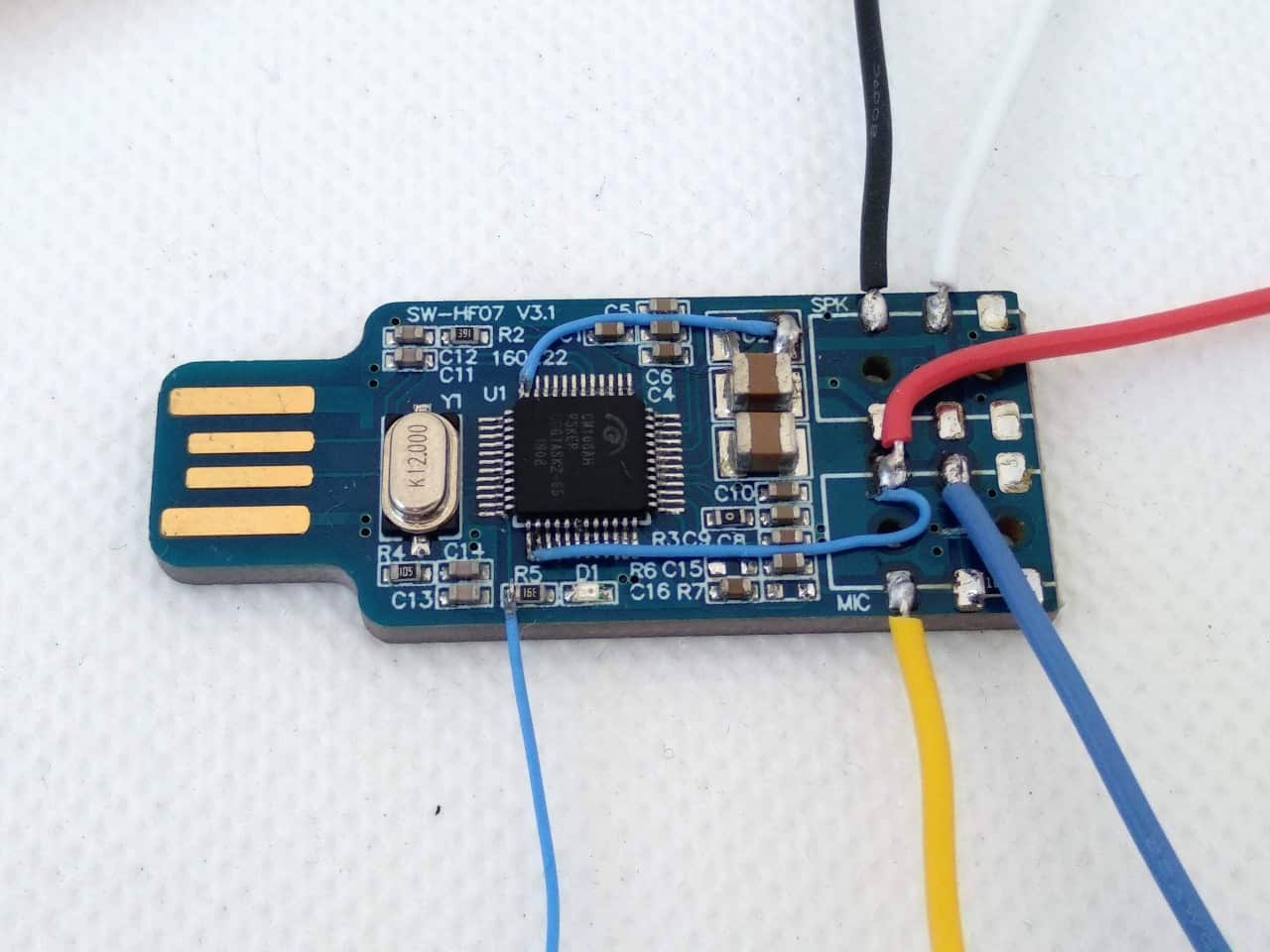
Step 6: Attach the two blue hookup wires for the indicator lights.
Click to enlarge.
How to wire up the front panel indicator lights.
1. The blinking green ” Keep Alive ” LED picks up 5v from the point shown using the thin wire on the left. This connects to the positive leg of the LED via a 1 K resistor and the negative leg of the LED goes to earth on the body of the Rpi.
2. The blue PTT indicator light is different from my other designs. It picks up an earth at the point shown on the FOB using the thicker blue wire on the right. This goes to the negative leg of the LED and the positive leg of the LED connects to 5v via a 4.7 K resistor.
Some degree of experimentation is of course possible with the values of the resistors if you want to adjust the intensity of the indicator lights.
Please note this way of adding indicator lights is different from the method described for my legacy nodes. This is because the PTT setting is set to Active High in this design.