How to Modify A CM108 Sound Fob For Allstar 2.

Modifying the CM108 sound card for use with Allstar. With surface mount resistors.

I am finding that using surface mount resistors instead of conventional ones makes for a much neater job visually and also it makes the modification of the fob much easier and quicker. The spacing between the solder pads on the CM108 is just right for utilising these tiny devices. Using a conventional transistor with its legs cut short also suits the solder pads. You can drop the three resistors and the transistor on to the board in about two minutes flat! 

I have a notion that nodes built in this way tend to have better sound quality, perhaps because the longer legs on the conventional resistors in my original design may attract RFI.

Step by step instructions below …


An unmodified CM108 sound fob. These are very cheap to buy.

modify CM108
My rough schematic - Click to enlarge.

Step 1: Carefully remove the green and pink sockets. This is best done with a heat gun, just apply the heat and let them float off. Don’t force it as this may damage the solder pads.

Click to enlarge.

Step 2. Remove resistors R6 and R7 as well as C2 at the top. Once this is done cut the tracks in the three places shown, you can use a multimeter before and after you cut the tracks to ensure the tracks are cut properly. I use a craft knife for this job

Click to enlarge

Step 3. Solder on the three surface mount resistors as shown above. This is actually very easy, just hold the resistor in place with tweezers, fix one end and then the other end is easy. Some sort of magnification helps. The resistor values are shown in my rough schematic above.

How to modify a CM108 for Allstar
Click to enlarge

Step 4. Attach the 2N3904 transistor, cut the legs short and attach the PTT wire first before you solder it on the board, I find this is a much easier process than using a surface mount transistor in this position.

Step 5. The back of the CM108 showing how the red PTT wire attaches. You can cover this afterwards with some insulating tape.

Click to enlarge

Step 6. The next stage is to attach the PTT wire { The lower one } and the COS wire to the legs of the chip as shown above. 

How to modify a CM!08 for Allstar
Step 7 - Click to enlarge
Step 7. Finally, just Add the four wires to hook the sound fob up to your radio.

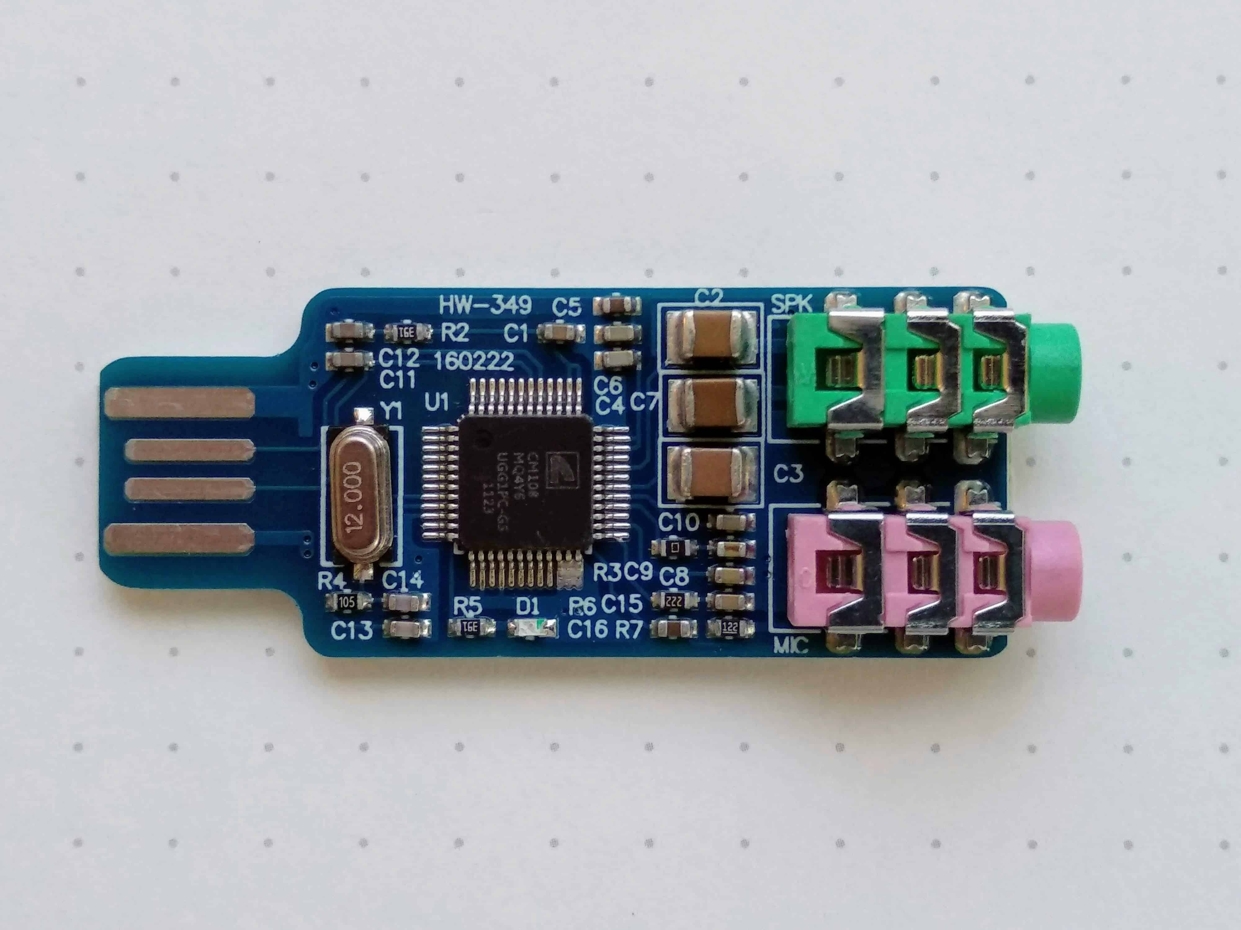
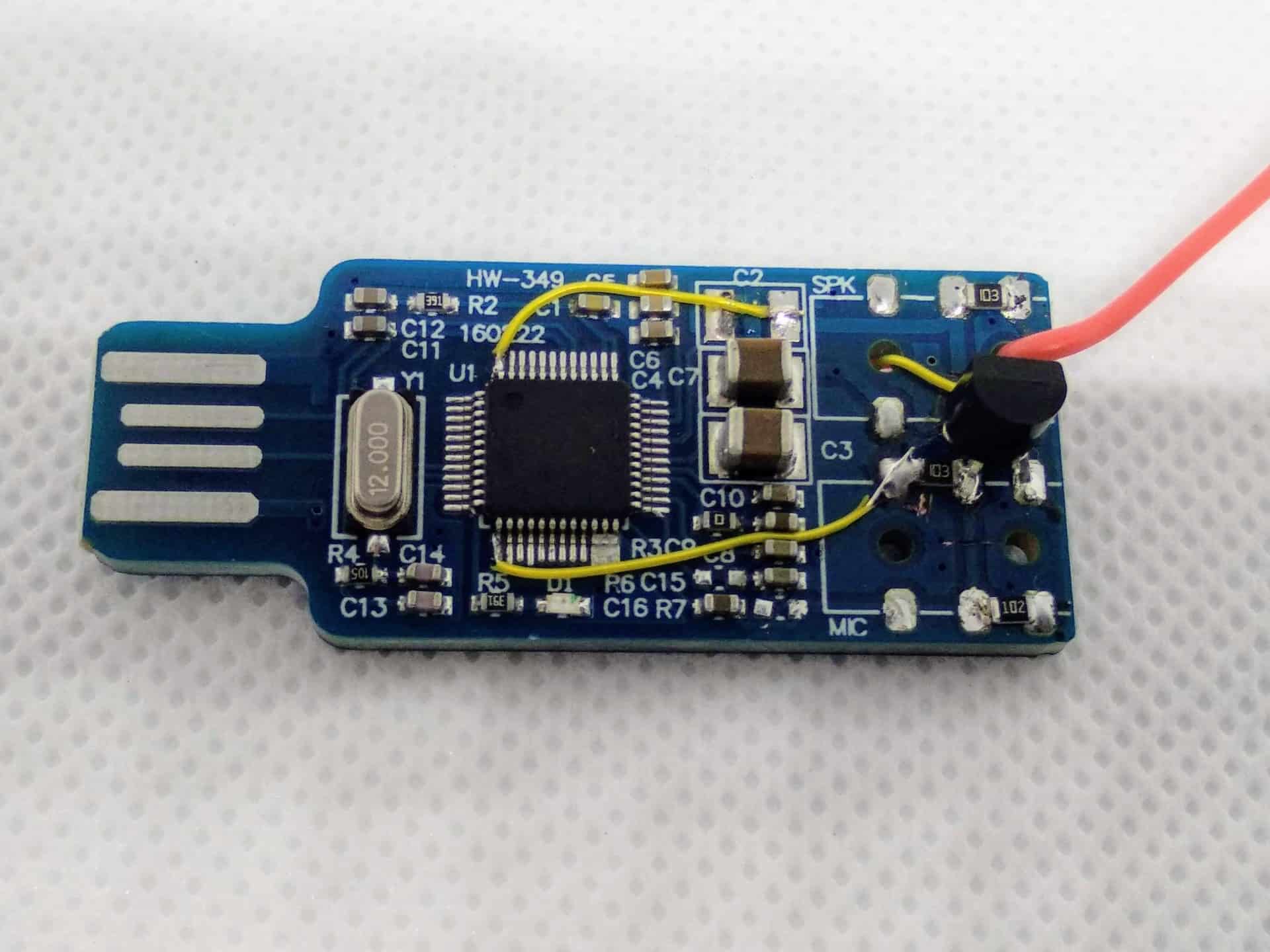
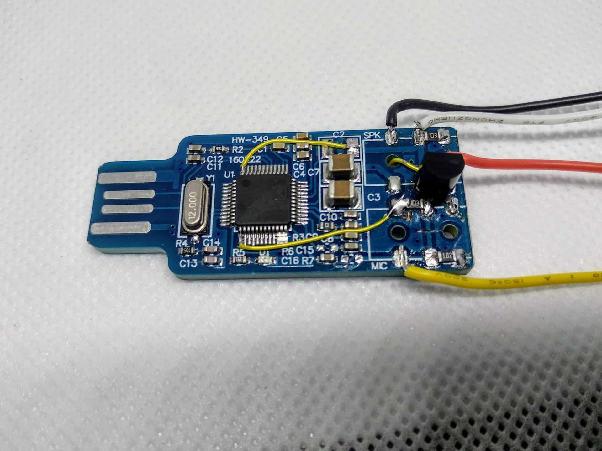
The above photo shows a completed sound fob which is ready to insert into a node, and this may be enough for your needs particularly if you use the excellent Node Remote app to control the node.

However, if you visit my More section you will find instructions on how to further modify the fob to include indicator lights for the front panel. This is a simple matter and no coding is required.LINK